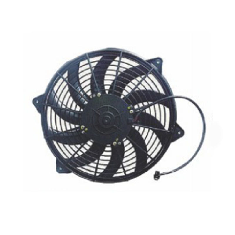
What Condenser Electronic Fans Actually Do in a Cooling System
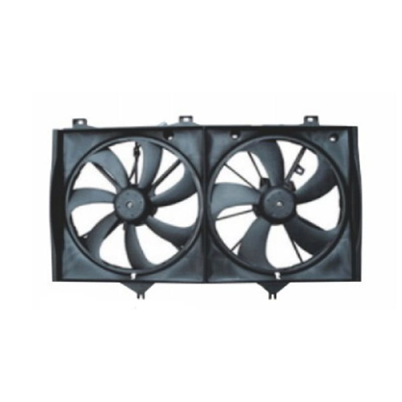
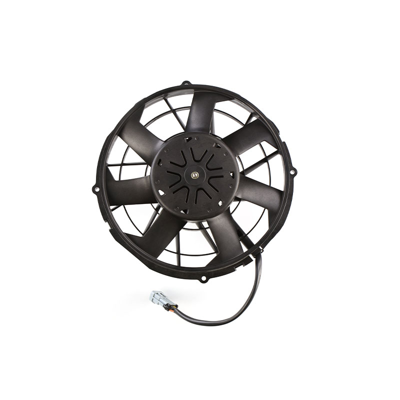
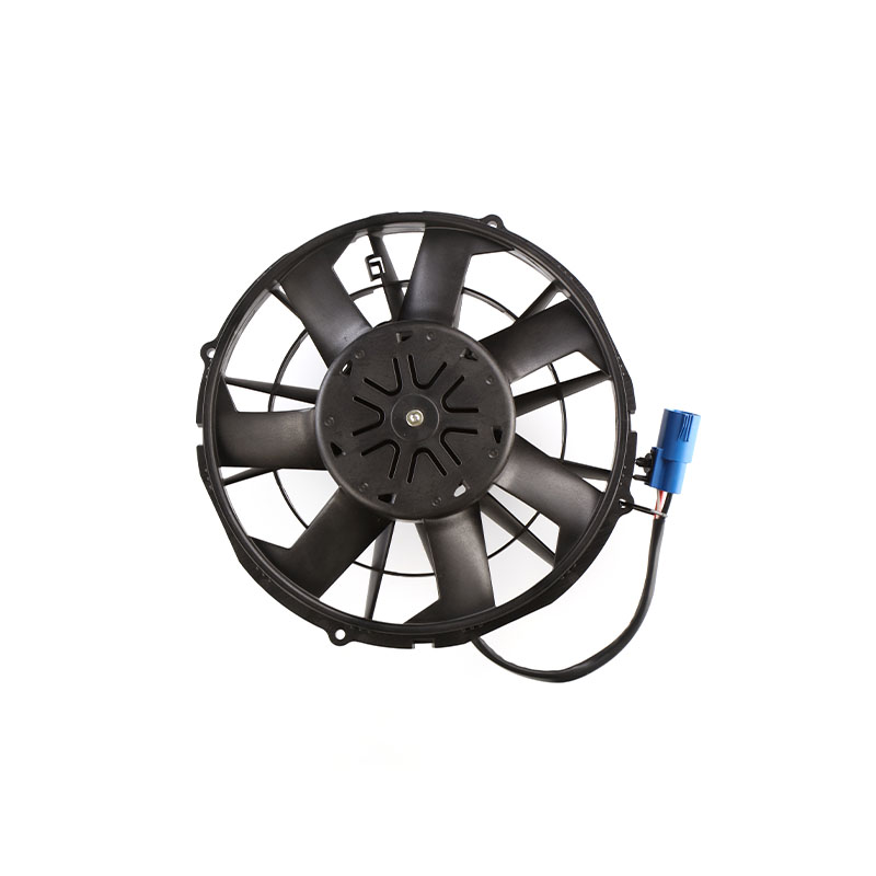
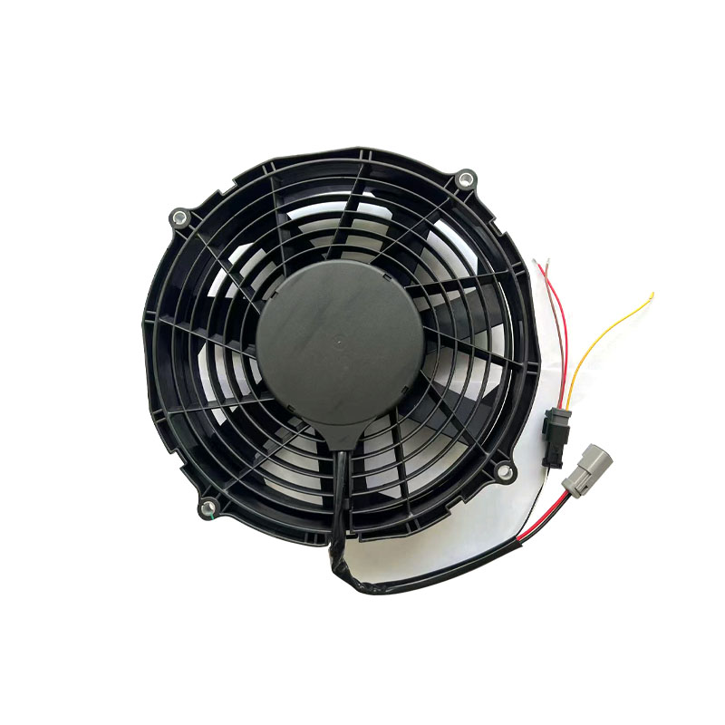
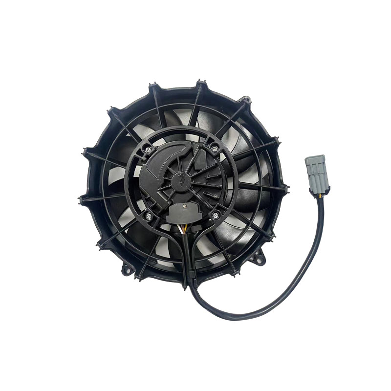
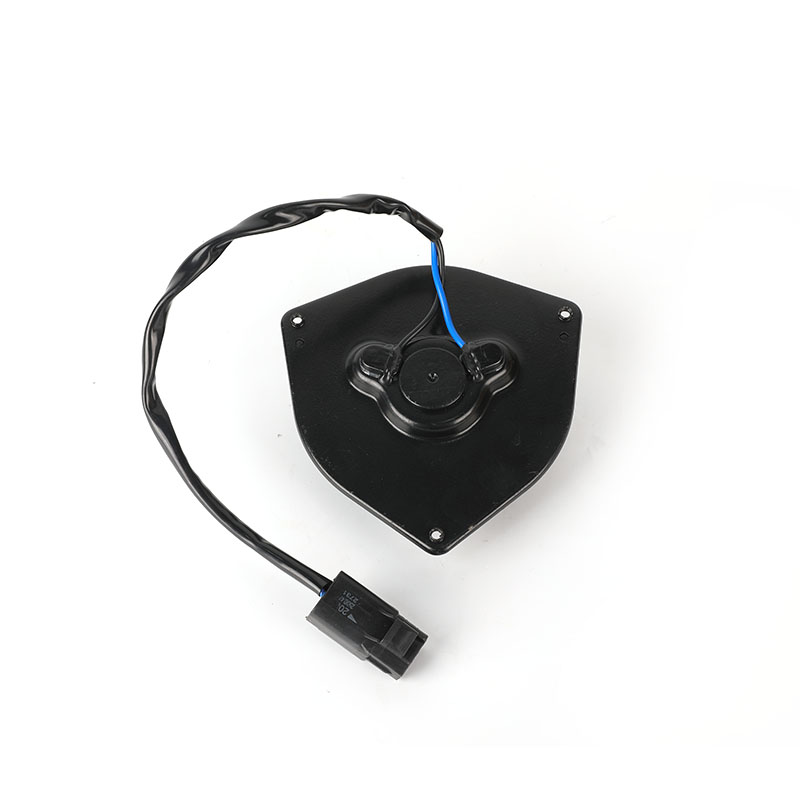
A condenser electronic fan is an electrically driven air-moving device mounted on or near the condenser coil of a refrigeration or HVAC circuit. Its task is straightforward but critical: force ambient air across the condenser fins so that refrigerant vapor can reject heat and condense into liquid. Without sufficient airflow, head pressure rises, compressor load increases, and system efficiency drops. In high-ambient regions, a weak or poorly matched fan can push a system into frequent high-pressure faults.
These fans are sometimes confused with evaporator fan assemblies, but the two operate in very different conditions. An evaporator fan moves cold, often humid air across the evaporator coil inside a refrigerated space. A condenser electronic fan moves hot air on the heat-rejection side, frequently outdoors, where dust, moisture, and temperature extremes are normal. That difference in working environment drives almost every design decision, from motor insulation class to bearing type and housing finish.
Typical installations include commercial refrigeration racks, cold storage condensing units, bus air-conditioning packs, rooftop HVAC condensers, and industrial heat-exchange skids. In each case, the fan must deliver stable airflow at a defined static pressure while surviving continuous duty. A fan that performs well on a bench test but overheats inside a cramped condenser shroud is not a successful selection.
40-60 Typical condenser approach temperature range in degrees Celsius for many refrigeration systems
24/7 Continuous duty expected in commercial cold storage and transport cooling
IP54+ Common ingress protection target for outdoor condenser fan motors
Because the fan sits on the heat-rejection side, its own motor is exposed to the very heat it helps remove. A practical rule is that every 10 degrees Celsius increase in motor winding temperature can reduce insulation life significantly. This is why condenser electronic fans usually prioritize high-temperature magnet wire, class F or class H insulation, and bearings that tolerate thermal cycling.
Hot refrigerant inside condenser coil Condenser electronic fan Hot air discharged
For sourcing engineers, the practical question is not whether a fan spins, but whether it maintains airflow after thousands of hours in a hot, dirty, vibrating enclosure. That is where motor type, bearing system, impeller geometry, and mounting rigidity become commercial differentiators.
Why Condenser Electronic Fans Outperform Generic Axial Fans in Heat Rejection
Not every axial fan is suitable for condenser service. A generic ventilation fan may move a similar open-air volume, but condenser applications impose three additional demands: higher static pressure capability, elevated ambient temperature tolerance, and long-term reliability without maintenance.
Static pressure capability
Condenser coils, fins, grilles, and shrouds create resistance. A fan rated at high free-air flow can collapse to a fraction of that flow once installed. Condenser electronic fans are selected with a pressure-flow curve that matches the installed system resistance. In practice, engineers look for a fan whose operating point sits near peak efficiency, not at the far right of the curve.
Thermal endurance
Motors used in condenser electronic fans are often specified with higher insulation classes and bearing lubricants rated for elevated temperatures. A fan moving 80 degrees Celsius air needs a different bill of materials than one moving 25 degrees Celsius air. This is a common failure point when buyers substitute a cheaper general-purpose fan.
Contamination tolerance
Outdoor condenser units face dust, pollen, rain splash, and occasional washdown. Ingress protection, coil coating, and drain paths matter. A fan with an open frame and unsealed bearings may last one season in a dusty environment, while a sealed or semi-sealed unit can run for years.
Selection factor
General axial fan
Condenser electronic fan
Static pressure design
Low to medium
Medium to high
Ambient temperature rating
Often 40-55 C
Commonly 60-80 C
Ingress protection
IP20-IP30 typical
IP44-IP55 common
Bearing system
Sleeve or ball
Ball or long-life sleeve
Expected duty
Intermittent
Continuous
The table above is not a universal law, but it reflects the general pattern in commercial refrigeration and HVAC condenser applications. Buyers who treat the fan as a commodity often discover the cost difference later through callbacks and replacements.
How to Match Fan Specifications to Real Condenser Operating Conditions
Selection starts with the system, not the fan catalog. A condenser electronic fan that is perfect for a bus air-conditioning pack may be entirely wrong for a stationary cold storage condensing unit. The following workflow helps narrow the field.
Step 1: Define the heat rejection load
Calculate the total heat to be rejected at design ambient conditions. This includes compressor power, refrigerant enthalpy change, and any motor heat inside the refrigerated space. The result determines the required air mass flow across the condenser.
Step 2: Measure or estimate system resistance
Coil fin density, grille free area, and shroud clearance all contribute to pressure drop. A dirty coil can double resistance over time. Select a fan whose curve still delivers adequate flow at the dirty-coil condition, not just the clean-coil condition.
Step 3: Choose motor type and voltage
AC fans are simple, robust, and widely available. DC and BLDC condenser electronic fans offer higher efficiency, variable speed control, and lower starting current. For transport refrigeration and bus air conditioning, DC is often mandatory because the power source is already DC. For stationary HVAC, AC remains common, but BLDC is gaining ground where energy codes or noise limits apply.
Step 4: Set ingress and temperature requirements
Outdoor condensers need at least IP44, and washdown or coastal installations may require IP55 or better. The motor insulation class should exceed the maximum expected ambient by a safe margin. Class F is a common minimum, with class H available for extreme conditions.
Step 5: Confirm mechanical fit and service access
Fan diameter, mounting hole pattern, blade clearance, and wiring exit position all affect installation. A fan that requires removing the refrigerant lines for service is a design mistake. Modular mounting brackets and plug-in connectors reduce field labor.
Practical tip: If you are unsure which model fits your project, send the system requirement, including voltage, airflow target, ambient temperature, and mounting space, for technical suggestion and price reference.
Heat load calculation System resistance Motor type and voltage IP and temp requirements Final fan selection Verify curve at dirty-coil condition
AC, DC, and BLDC Condenser Electronic Fans: A Practical Comparison
The motor is the heart of the fan. Choosing between AC, DC brushed, and BLDC electronically commutated motors affects efficiency, controllability, maintenance, and total cost of ownership.
Attribute
AC induction
DC brushed
BLDC
Efficiency at part load
Moderate
Low to moderate
High
Speed control
Limited
Simple voltage control
PWM or 0-10V
Brush wear
None
Yes
None
Starting current
High
Moderate
Low
Typical use
Stationary HVAC
Legacy transport
Modern transport and efficient HVAC
For DC condenser electronic fans, the available bus voltage often dictates the design. A 24V system is common in buses and trucks, while 12V remains standard in smaller vehicles. Stationary systems may use 48V DC for efficiency and safety, or retain 110V/220V AC for compatibility with existing power distribution.
BLDC fans are increasingly specified because they can modulate speed in response to condensing pressure. Instead of cycling on and off, the fan slows down in cool weather and speeds up in peak heat. This reduces noise, energy use, and thermal stress on the motor. The trade-off is a more complex control interface, which matters for buyers who lack electronics expertise.
Sourcing note: When comparing quotations for condenser electronic fans, ask for the operating point, not just the nominal airflow. A fan quoted at free-air delivery may deliver far less in the installed condenser.
Key Specifications Buyers Should Verify Before Ordering
Purchase orders for condenser electronic fans often go wrong because a critical specification was left to assumption. The following checklist covers the items that most frequently cause fit, performance, or reliability problems.
Airflow and static pressure
Request a fan curve that shows airflow against static pressure. Confirm the intended operating point and the expected dirty-condition resistance. A single airflow number without pressure context is not enough for condenser service.
Motor electrical data
Verify voltage, frequency, phase, current draw, and speed. For DC fans, confirm the acceptable voltage range, because bus voltage can vary widely in transport applications. For AC fans, check whether the motor is capacitor-run or shaded-pole, as starting torque differs.
Temperature and ingress rating
Confirm maximum ambient temperature, insulation class, and IP rating. If the fan will be washed down, verify the IP rating applies to the motor and not just the housing. Some suppliers rate the enclosure while leaving the motor exposed.
Bearing system and life expectancy
Ball bearings generally handle higher temperatures and radial loads than sleeve bearings. Sleeve bearings can be quieter and cheaper but may require specific mounting orientation. Ask for L10 bearing life or a comparable reliability statement.
Mechanical interface
Check fan diameter, mounting hole spacing, blade tip clearance, and rotation direction. Confirm the airflow direction, because reversing a fan can reduce performance dramatically. Verify the wiring exit and connector type against the harness on the production line.
Noise and vibration
Noise matters in bus air conditioning and residential HVAC. Vibration matters everywhere, because it accelerates bearing wear and can crack mounting points. Ask for balance grade and any vibration test data.
Specification
Why it matters
Common pitfall
Operating point
Determines real airflow in the condenser
Using free-air flow only
Voltage range
Ensures stable operation under supply variation
Assuming nominal voltage is always available
IP rating scope
Protects motor in wet or dusty environments
Rating applies only to the housing
Bearing type
Affects life at high temperature
Sleeve bearing in hot, vertical mounting
Rotation and airflow direction
Prevents reversed installation
Assuming all fans blow the same way
Condenser Electronic Fans Versus Evaporator Fans: What Changes in Selection
The two fan types are often purchased by the same team, but they should not be selected with the same criteria. The table below summarizes the practical differences that affect specification and sourcing.
Item
Condenser electronic fans
Evaporator fans
Working position
Condenser unit, heat rejection side
Evaporator coil side, cooling side
Working environment
High temperature, outdoor, dirty
Cold, humid, enclosed cabinet
Core mission
Dissipate system heat
Distribute cold air
Typical ambient
Up to 80 C or higher
Often below 10 C
Moisture exposure
Rain, washdown, condensation
Defrost water, high humidity
Noise sensitivity
Moderate to high
High in occupied spaces
Because evaporator fans run in cold, humid air, they may face ice buildup and defrost cycles. Condenser electronic fans face the opposite problem: constant heat and outdoor contamination. A motor optimized for one environment may fail prematurely in the other. This is why buyers should specify the application, not just the dimensions, when requesting quotations.
For a deeper look at the cooling-side fan family, the evaporator fan product line covers the cold-air circulation side of the same refrigeration circuit. Understanding both sides helps procurement teams avoid cross-compatible but misapplied parts.
Common Failure Modes and How to Prevent Them
Field failures of condenser electronic fans usually trace back to a small number of causes. Knowing them helps buyers write better specifications and evaluate supplier quality.
Bearing seizure
Heat, dust, and vibration degrade lubricant. A fan that runs hot may lose lubricant faster than expected, leading to increased friction and eventual seizure. Specifying high-temperature grease and a sealed or shielded bearing arrangement reduces this risk.
Winding insulation breakdown
Thermal cycling and moisture ingress can degrade insulation. Once insulation fails, the motor shorts and the fan stops. Class F or H insulation, proper varnish treatment, and effective sealing extend winding life.
Blade fatigue and cracking
Repeated vibration and thermal expansion can crack blades, especially in large-diameter fans. Glass-filled nylon or metal impellers with proper balance and stiffness are common solutions. A cracked blade can cause severe imbalance and damage the motor.
Connector and wiring failure
Vibration can loosen connectors or fatigue wire strands. Strain relief, locking connectors, and flexible wire routing improve durability. In transport applications, this is a frequent warranty issue.
Control electronics failure
BLDC fans include driver electronics that are sensitive to voltage spikes and moisture. Potting, conformal coating, and transient protection improve survival in harsh electrical environments.
Bearing Most common mechanical failure point in condenser fan service
Insulation Key electrical failure mode under thermal cycling
Connector Frequent warranty issue in vehicle applications
How to Evaluate a Condenser Electronic Fan Supplier
For B2B buyers, the fan itself is only part of the purchase. The supplier's ability to support customization, quality control, and after-sales service determines total cost and project risk.
Engineering support
Does the supplier ask for system conditions before quoting, or only for a part number? A supplier that requests airflow, static pressure, ambient temperature, and voltage is more likely to recommend a workable fan. Custom condenser electronic fans often require adjustments to voltage, wiring, mounting, or speed control.
Quality control process
Ask about incoming material inspection, motor testing, balance checks, and final performance verification. A supplier that tests every fan at the operating point provides more confidence than one that only samples.
Certification and documentation
Depending on the market, fans may need CE, UL, RoHS, or other approvals. Request certificates and test reports early, because retrofitting certification is expensive. Documentation also matters for warranty and traceability.
Customization capability
ODM and OEM projects often require specific connectors, lead lengths, labels, and packaging. A supplier with in-house engineering and flexible production can accommodate these without long lead times. Ask for a sample lead time and a production lead time separately.
After-sales response
When a fan fails in the field, response time matters. Ask how the supplier handles failure analysis, replacement, and corrective action. A clear process reduces downtime and protects the buyer's reputation with end users.
Procurement tip: Request a quotation that separates unit price, tooling, sample cost, and packaging. This makes it easier to compare suppliers and to identify hidden costs before placing a production order.
Frequently Asked Questions About Condenser Electronic Fans
Q1: What factors affect condenser electronic fans price?
Motor type, fan size, IP rating, bearing system, order quantity, and custom requirements all influence cost. A BLDC fan with sealed bearings and a high IP rating costs more than a basic AC fan of the same diameter. As a manufacturer, NicetyMotor can offer competitive wholesale pricing; send your specification for a detailed quotation.
Q2: Can I order custom condenser electronic fans for special refrigeration equipment?
Yes. Custom voltage, dimensions, wiring, connectors, mounting brackets, and speed control are common ODM and OEM requests. Provide the system conditions and mechanical envelope, and the engineering team can propose a matched fan solution.
Q3: What is the typical lifespan of a condenser electronic fan?
Lifespan depends on ambient temperature, duty cycle, contamination, and bearing type. A well-specified fan in a clean, moderate environment can run for tens of thousands of hours. In hot, dusty conditions, life may be shorter. Bearing life and insulation class are the best indicators to compare.
Q4: How do I tell condenser electronic fans and evaporator fans apart during replacement?
Check the location in the circuit. The condenser fan sits on the heat-rejection side and moves hot air away from the coil. The evaporator fan sits on the cooling side and circulates cold air. Markings, connectors, and mounting may also differ. When in doubt, trace the refrigerant lines and confirm which coil is which.
Q5: What information should I provide to get an accurate quotation?
Provide voltage, airflow or heat load, static pressure, ambient temperature, IP requirement, mounting dimensions, and quantity. If available, include a drawing or photo of the existing fan and the connector type. The more complete the input, the faster and more accurate the quotation.
Q6: Are DC condenser electronic fans suitable for bus air conditioning?
Yes, DC and BLDC fans are widely used in bus and transport air conditioning because the vehicle provides a DC power source. The key is to confirm the voltage range, because bus electrical systems can vary. IP rating and vibration resistance are also important in mobile applications.
Bringing the Selection Process Together
Condenser electronic fans are small components with an outsized effect on refrigeration and HVAC performance. A fan that matches the system's airflow, pressure, temperature, and contamination profile keeps condensing pressure stable and protects the compressor. A fan selected on price alone often becomes a recurring maintenance cost.
For buyers, the most reliable approach is to define the operating conditions first, then compare fan curves, motor types, ingress ratings, and bearing systems against those conditions. Supplier engineering support, quality control, and customization capability are as important as the fan's nominal specifications.
If you are sourcing qualified condenser electronic fans for HVAC, refrigeration, or vehicle air-conditioning projects, contact NicetyMotor to request the latest wholesale price list, datasheet, and custom solution. The sales and engineering team will review your inquiry and respond promptly.
.section-block {
font-family: 'Segoe UI', Roboto, 'Helvetica Neue', sans-serif;
font-weight: 400;
line-height: 2;
}
.section-block h2 {
font-size: 20px;
font-weight: 700;
text-align: left;
margin-bottom: 10px;
color: #da251c;
border-bottom: 3px solid #da251c;
padding-bottom: 6px;
}
.section-block h3 {
font-size: 18px;
font-weight: 700;
text-align: left;
margin-top: 5px;
margin-bottom: 5px;
color: #333333;
}
.section-block h4 {
font-size: 16px;
font-weight: 500;
text-align: left;
margin-top: 10px;
margin-bottom: 5px;
color: #da251c;
}
.section-block p {
margin-bottom: 5px;
font-size: 16px;
color: #333333;
}
.section-block ul,
.section-block ol {
margin-top: 8px;
margin-bottom: 8px;
}
.section-block li {
list-style-position: inside;
font-size: 16px;
color: #333333;
}
.section-block ul li {
list-style-type: disc;
}
.section-block ol li {
list-style-type: decimal;
}
.section-block strong {
font-weight: 500;
}
.section-block table {
width: 100%;
border-collapse: collapse;
margin-top: 10px;
margin-bottom: 10px;
}
.section-block td,
.section-block th {
text-align: center;
font-size: 16px;
border: 1px solid #dddddd;
padding: 8px;
}
.section-block th {
background-color: #da251c;
color: #ffffff;
font-weight: 500;
}
.section-block td {
background-color: #fafafa;
color: #333333;
}
.section-block .card-row {
display: flex;
gap: 12px;
margin-top: 12px;
margin-bottom: 12px;
flex-wrap: wrap;
}
.section-block .data-card {
flex: 1;
min-width: 160px;
background: #ffffff;
border: 2px solid #da251c;
border-radius: 10px;
padding: 14px;
text-align: center;
box-shadow: 0 2px 8px rgba(0,0,0,0.06);
}
.section-block .card-value {
display: block;
font-size: 20px;
font-weight: 700;
color: #da251c;
margin-bottom: 6px;
}
.section-block .card-label {
display: block;
font-size: 14px;
color: #333333;
line-height: 1.6;
}
.section-block .highlight-box {
background: #fdf0ef;
border-left: 6px solid #da251c;
border-radius: 6px;
padding: 12px 16px;
margin-top: 12px;
margin-bottom: 12px;
}
.section-block .highlight-box p {
margin-bottom: 0;
font-size: 16px;
color: #333333;
}
.section-block svg text {
font-family: 'Segoe UI', Roboto, 'Helvetica Neue', sans-serif;
}
.section-block svg .svg-title {
font-size: 16px;
}
.section-block svg .svg-body {
font-size: 14px;
}


 English
 Español
 عربى
عربى русский